
What Is a Multi Stage Cylinder and How Does It Work?
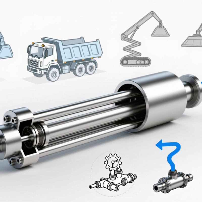
A Multi Stage Cylinder creates a long working stroke from a compact retracted package. Its nested sections, called stages, extend one after another as hydraulic pressure moves the piston assembly. Picture a series of metal tubes sliding outward from a single barrel. The result is useful where installation space is short but reach must be substantial, including dump bodies, lifting platforms, and material-handling equipment.
Industry data helps explain why selection deserves care. The National Fluid Power Association’s U.S. fluid-power industry statistics track shipments and market activity across hydraulic and pneumatic equipment. That context points to a broad industrial role, not a guarantee that one cylinder design suits every machine. The U.S. Department of Energy’s Improving Pumping System Performance sourcebook also stresses system-level efficiency: component performance depends on how equipment is selected, operated, and maintained. A cylinder’s bore, stage sequence, load, pressure, and mounting all affect real-world behavior.
The principle is simple. The details are not. Different designs may extend stages in different sequences, and load capacity can change as the cylinder extends. That distinction is easy to overlook. This guide explains the main parts, operating sequence, common configurations, and practical selection checks. It also notes where published specifications should be verified with the manufacturer, because “multi-stage” does not describe one universal design. A careful comparison starts with the required stroke, retracted length, duty cycle, and operating conditions—not appearance alone.
What Is a Multi-Stage Cylinder?
A multi-stage cylinder is a linear actuator built from several nested, hollow sections, often called stages. When retracted, the sections slide inside one another, keeping the unit short. Under hydraulic pressure, they extend in sequence; in many designs, the larger stage moves first, followed by narrower sections. This arrangement provides a long working stroke where a conventional cylinder would be too long to install. Think of a tipper body lifting: a compact cylinder extends upward as each sleeve emerges. Some cylinders retract by gravity or a spring; others use pressure in both directions. The exact sequence depends on the design.
The extra reach has trade-offs. As stages extend, the cylinder’s support becomes less rigid, so side loads and mounting alignment matter. A practical inspection checks for uneven wear, damaged seals, and oil leaks—not just whether the cylinder moves. For pneumatic versions, supply-air quality matters too. The U.S. Department of Energy’s Improving Compressed Air System Performance sourcebook reports that leaks can waste 20–30% of compressor output in poorly maintained systems. That figure describes the air system, not a cylinder’s efficiency, but it shows why leak checks are worthwhile. The compact design is useful, though its limits deserve attention.

Key Components and Their Functions
What Is a Multi Stage Cylinder and How Does It Work?
Key Components and Their Functions
A multi-stage cylinder contains nested sleeves that extend one after another, creating a long stroke from a short retracted length. The barrel or outer stage guides the assembly and contains hydraulic pressure. Smaller inner stages provide additional reach. Piston seals limit fluid bypass, while wear rings keep metal surfaces aligned. End stops prevent stages from separating. Ports direct fluid into or out of the cylinder. ISO 1219-1:2012 provides standardized symbols for representing these hydraulic components in circuit diagrams.
During extension, pressurized fluid acts on a stage’s effective piston area. A useful sizing check is force = pressure × area: at 20 MPa and 100 cm², theoretical force is 200 kN. Actual output is lower because of friction, seal drag, and pressure losses. Stage sequence depends on cylinder design and load. Single-acting versions commonly retract under gravity or an external load; double-acting versions use hydraulic pressure for retraction. ISO 4413:2010 sets general safety requirements for hydraulic systems, but it does not provide one universal cylinder efficiency figure.
Tips: Check each stage’s rated pressure, stroke, and load before selecting a cylinder. Keep the rod clean; a small dent can damage a seal. Treat force calculations as estimates, not guarantees. Testing under the real mounting angle and load can reveal issues that a neat drawing misses.
What Is a Multi Stage Cylinder and How Does It Work?
A telescopic multi-stage cylinder uses nested sections that extend one after another to provide a long stroke from a compact retracted length.
The chart shows a normalized example: nested stages generally have progressively smaller bores. The index is illustrative, not a set of engineering dimensions. The barrel houses the stages, the piston and seals help create hydraulic force and limit leakage, and the ports direct fluid. Stage sequence and dimensions vary by design and load.
How a Multi-Stage Cylinder Extends and Retracts
What Is a Multi Stage Cylinder and How Does It Work?
How a Multi-Stage Cylinder Extends and Retracts
A multi-stage cylinder uses nested tubes, called stages, to create a long stroke from a short closed length. Hydraulic pressure usually extends the largest-diameter stage first; smaller stages follow as the assembly lengthens. This sequence uses differences in piston area and pressure, though some designs use internal stops or sequencing valves.
Watch the joints closely. Dirt or side loading can damage seals and cause uneven movement.
Retraction depends on the cylinder design. In a single-acting model, gravity or the supported load pushes the stages back into their sleeves. A double-acting model uses hydraulic pressure to retract them, often in reverse sequence.
ISO 6020-1:2018 gives 16 MPa as a nominal pressure benchmark for its medium-series cylinders; it is not a universal rating for telescopic designs. At that pressure, a 50 mm bore produces about 31 kN of theoretical force, before friction and losses. Real output will be lower.
Engineers should check each stage’s pressure limit, load alignment, and retraction conditions rather than relying on the largest-stage figure alone.
Common Designs and Operating Configurations
Multi-stage cylinders are commonly built as telescopic assemblies, with hollow tubes nesting inside a larger barrel. When pressure enters, the largest stage often extends first, followed by narrower stages. This arrangement provides a long stroke from a compact, retracted package. It suits dump bodies, lifting platforms, and equipment with limited installation space. Small clearances matter.
Single-acting designs use fluid pressure to extend, then rely on gravity or an external load to retract. They are simple, but return can be slow or uneven if the load shifts. Double-acting versions apply pressure to both sides, powering extension and retraction. They offer more control, though plumbing and seals become more involved. Not every job needs that complexity.
Stage sequencing depends on bore areas, load, friction, and circuit design. As stages move, available force and speed change; smaller stages often provide less force but more travel. Designers check pressure ratings, side loading, mounting alignment, and end-of-stroke cushioning. Real loads vary. A cylinder may look adequate on paper yet bind when the load sits off-center. That risk is easy to underestimate. Maintenance records can reveal leaks, scoring, or uneven extension before problems become obvious.
What Is a Multi Stage Cylinder and How Does It Work? - Common Designs and Operating Configurations
| Design or configuration | How it works | Typical characteristics | Common applications | Key design considerations |
|---|---|---|---|---|
| Single-acting telescopic | Hydraulic pressure extends nested stages, generally in sequence. Retraction is supplied by an external force such as gravity or the supported load. | Provides a long stroke from a short retracted length. Extension force and speed can vary between stages because each stage has a different effective piston area. | Dump bodies, lifting platforms, and equipment where the load can help retract the cylinder. | The load and mounting arrangement must provide adequate retraction force. Check stage sequence, stability, side loading, and end-of-stroke cushioning. |
| Double-acting telescopic | Hydraulic pressure is used to extend and retract the stages. Internal passages and stage geometry route fluid to the appropriate working areas. | Allows powered movement in both directions and does not rely solely on gravity for retraction. The design is more complex than a single-acting version. | Mobile machinery and installations where controlled, powered retraction is required. | Confirm the required force in both directions, internal fluid routing, seals, available pressure, and the manufacturer's specified operating sequence. |
| Sequential stage operation | Stages move one after another. In many telescopic hydraulic designs, stage order is determined by effective area, pressure, mechanical stops, and internal sequencing features. | Produces a compact retracted package and a long overall stroke. Stage speeds may differ as fluid flow acts on changing effective areas. | Applications requiring substantial extension from a limited installation length. | Do not assume identical force or speed at every stage. Verify the stage-by-stage performance data and allowable operating orientation. |
| Synchronized or controlled extension | Multiple stages or cylinders are arranged with hydraulic circuits or mechanical features intended to coordinate their movement. The exact method depends on the system design. | Can help control relative movement, but synchronization accuracy depends on circuit design, load, fluid conditions, and component tolerances. | Lifting systems and equipment where coordinated movement is important. | Assess load sharing, flow division, alignment, and the need for position feedback or a leveling control system. |
| Multi-stage pneumatic cylinder | Compressed air drives a sequence of nested or linked sections, depending on the cylinder construction. Air pressure and flow govern movement. | Can provide extended travel with a relatively short retracted length. Pneumatic systems are compressible, so motion and positioning can be more load-sensitive than in hydraulic systems. | Automation equipment and light-duty applications suited to compressed-air actuation. | Check operating pressure, air consumption, load limits, cushioning, and whether the required motion and positioning accuracy suit pneumatic control. |
| Tandem cylinders (multiple pistons on a common rod) | Two or more piston areas act on a common rod, typically to increase available force without increasing the bore of a single piston. This is a multi-piston arrangement rather than a telescopic stage design. | Can increase output force within a similar bore size, but generally does not provide the long stroke-to-retracted-length advantage of a telescopic cylinder. | Applications needing higher linear force where installation length and stroke requirements permit a tandem layout. | Confirm that pressure reaches the intended piston areas and account for total cylinder length, seals, flow requirements, and mounting loads. |
Note: “Multi-stage cylinder” often refers to a telescopic cylinder with nested moving sections. Tandem cylinders also use multiple piston areas, but have a different construction and operating purpose.
Applications and Selection Factors
A multi-stage cylinder uses nested sections that extend in sequence, providing a long stroke from a relatively short retracted length. This makes it useful where space is limited but movement must cover a considerable distance. Common applications include dump trailers, lifting platforms, agricultural equipment, and material-handling systems. A platform may need to rise several meters while the cylinder fits beneath its frame. Space is tight.
Selection starts with the required force and stroke. Check the load throughout the full movement, since leverage and load distribution can change as equipment rises. Confirm the cylinder’s pressure rating, mounting points, retracted length, and available clearance. Uneven loading can create side forces that a standard cylinder may not tolerate. Where alignment is uncertain, allow for a suitable guiding structure rather than relying on the cylinder alone.
Operating speed and duty cycle matter too. More stages can mean more connections and seals, so maintenance access deserves attention. Consider temperature, dust, moisture, and the hydraulic fluid used in the system. The first specification is often incomplete; measure the actual installation and verify the load case before ordering. Not always easy. A qualified engineer can review calculations and confirm that the chosen cylinder suits the equipment and operating conditions.